Machine Safety
Machine Safety is the protection of personnel or plant assets from damage or death. Components of machine safety include:
- Organizational safety (Requirements for safety shoes, FRC, safety glasses, etc.)
- Passive Safety (guard rails, covers for moving parts, gates)
- Functional Safety (Protection from hazards due to incorrect functioning of the industrial machinery)
Functional Safety
This article will focus on Functional Safety for the factory automation environment. Common components for Functional Safety systems include safety relays, specialized safety PLCs, and components with built-in safety.
- Safety relays are the original safety go-to technology. Early safety standards required implementation only with discrete wiring and relay technology.

- Specialized safety PLCs, designed to exceed national standards on safe design for software/firmware-based safety control.
- Components with built-in safety can include specialized I/O with built-in error detection technology, dual inputs or outputs to continue to function even in the presence of a failure, and devices that fail to a chosen safe state.
Safety Relays – “Classic” safety
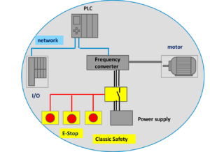
In the beginning of the PLC era, safety standards and regulations prohibited any use of microcontrollers, software, or communication networks for safety implementations. Safety was hard-wired and based on relay technology. Now, the use of PLCs and field bus technology have been “proven in use” in millions of applications, so the reliability records are substantial. National safety standards, such as NFPA 79 and IEC 61508, have been modernized to allow safety PLCs and safety communications to be used in safety systems. There are now many accepted ways to implement safety for industrial applications.
Specialized Safety PLCs
Safety PLCs are specialized PLCs that provide critical control in an automation environment. They are designed to detect possibly dangerous situations and allow the safety program to take actions to bring the system to a safe state. Safety PLCs emphasize internal diagnostics that allows them to detect improper operations with the PLC itself. Part of the safety diagnosis is the monitoring of program flow control and data verification to ensure that the safety PLC program and operating system have not been corrupted. Safety PLCs must meet International standards for PLC design and reliability. They must be approved by a Certifying body such as TUV in Germany or UL in the US.
Components with Built-in Safety
Safety components support Functional Safety by employing one of the “proven in use” safety architectures. Three of the most common safety architectures are listed below.
DTT and ETT Valves
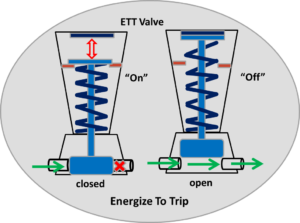
The first safety architectures used in safety I/Os were the simple automatic switch/valve implementations know as ETT (Energize To Trip) and DTT (De-Energize To Trip). They are devices that are designed so that on failure the device fails to the selected state. DTT valves open when they are in the “on” state. When the power drops down, the valve is de-energized and closes (trips). ETT valves open when power is “off”, they close (trip) when the valve power is on.
RMD Principles of Design
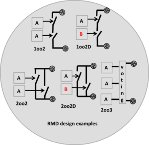
The second safety architecture is based on the idea of RMD (Redundancy, Multiplicity, and Diversity).
- Redundancy – use of identical Safety Instrumented Functions to achieve higher safety reliability.
- Multiplicity – use of multiple shutdown paths or protective devices.
- Diversity – uses different types of devices to reduce the chances that redundant devices can be affected by common failure modes. Usually, different technologies are chosen
The following table shows safety architectures and what objectives they help meet.
| Architecture | Number of units | Safety Fault Tolerance | Availability Fault Tolerance | Objectives |
|---|---|---|---|---|
| 1oo1 | 1 | 0 | 0 | Standard unit |
| 1oo2 | 2 | 1 | 0 | High Safety |
| 2oo2 | 2 | 0 | 1 | High Availability |
| 1oo1D | 1 | 1 | 0 | High Safety |
| 2oo3 | 3 | 1 | 1 | High Availability, High Safety |
| 2oo2D | 2 | 1 | 1 | Safety and Availability, bias toward Availability |
| 1oo2D | 2 | 1 | 1 | Safety and Availability, bias toward Safety |

RMD nomenclature is usually something like 1oo2D (One out of Two Diverse), which refers to the module having 2 units, with 2 different technologies(Diversity). The RMD principles are used together to allow the system designer to balance system availability against system safety.
Periodic Testing
In Safety Systems, it can be important to know that an input or output will react correctly when it is called upon to do its’ job. For example, we need to know that a critical valve will close when it is told to close. This can be achieved by periodically testing the valve function via a “partial valve stroke” which is trend monitored so that we know the valve will react when it is closed. This can be done automatically by a Safety-controller. (Trend monitoring can also use for allowing predictive maintenance when it is convenient for the user.)
Functional Safety System
We have just looked at the common components of Functional Safety Systems. Typical safety systems rely on a mix of these components. Next, we will compare conventional safety systems(those with a standard PLC and a safety PLC) vs using a PLC that combines safety and non-safety operations into one unit. Safety Basics – Conventional vs Combined system
 Gain a deeper understanding of PROFINET by attending a PROFINET Certified Network Engineer Course.
These certification classes are intense, hands-on courses. You will learn how the underlying technology works from the application to the frame level. After passing both a practical and written exam, you become certified.
For more information, contact us or visit our website.