Editor’s note: This article is an excerpt from the PROFINET Developer Workshop offered by the PROFI Interface Center. For more information on this or other advanced topics, contact them at pic.industry@siemens.com.
Alarms, Diagnostics, Errors… these terms get thrown around a lot when people discuss how to communicate when bad things happen on the network. But what do they really mean? In this article, we’ll take a look at what kind of information is conveyed in alarms, and how you can leverage it as a developer.
Background
PROFINET devices accomplish 99.9% of their communication via the cyclic, real-time communications channel. Data is produced according to a pre-defined format, and it’s sent on a schedule that doesn’t care if the data changes. This is a great way to communicate data that changes constantly, but it imposes a lot of overhead on data that only changes very rarely.
On-Demand PROFINET Developer Training
The PROFI Interface Center provides product development training for your team tailored to meet your needs.
These classes are intensive, immersive experiences designed to bring a development team up to speed on PROFINET communications and best practices. The lab exercises can be used as the groundwork for developing a new PROFINET device, while the concepts can be used to implement a device on an existing platform.
For more information, contact us or visit: http://ondemand.profiinterfacecenter.com/
Alarms are really useful for the 0.1% of communication needs that can’t be handled in that pre-defined cyclic format. They’re event-driven, so a PROFINET device will only send them if an event happens that the PROFINET controller needs to know about. For instance, it’d be inefficient to pack information about a redundant power supply’s operating state into the cyclic channel, so most devices don’t (power supplies fail relatively rarely). But if one of the inputs to that redundant supply goes down, the device can send one alarm to the controller to let it know what’s happened. This keeps the rarely-changing power supply data out of the cyclic channel, saving bandwidth and processing overhead.
This article covers how the content of these alarms is defined and how it’s handled in a typical PROFINET controller. We’ll start by modifying a GSDML file to define alarm content and then see how that data is pulled in to the Siemens TIA Portal configuration software. We’ll use a Siemens S7 PLC in this example, but the concepts of how to handle alarms are constant across all PROFINET Controller vendors.
PROFINET Alarm Structure
Before we can talk about the fun stuff, we first need to understand the way PROFINET alarms are put together. Alarms can encode data in two different ways, as either a Diagnostic Alarm or a Process Alarm. We’re going to focus on Diagnostic Alarms in this lab. Within Diagnostic Alarms, there are two formats that are differentiated by their User Structure Identifier (USI), the Standard Format and a User Defined Format. In this exercise, we will only cover the Standard USI Format (0x8000).
Once we can say that the alarm will be a Diagnostic using the Standard Format, there are some options about how to encode the Standard Format Data. At the top level, there are Channel Errors, which can be further differentiated by an Extended Channel Error. Both of those values must be described in the GSDML file for a PLC to process them.
There’s one more layer of detail in a Diagnostic Alarm, though: the “Channel Error Additional Value”. The format of this Additional Value is defined in the GSDML file, but the actual value sent to the PLC will depend on the conditions in the device when the alarm was sent.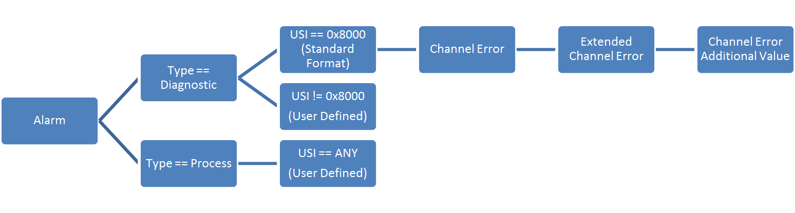
For instance, a device may raise a Diagnostic Alarm with:
- A ChannelError “Overheat” (A high-level description of the problem)
- An ExtendedChannelError “Output Transistor 1” (detailed description of the problem)
- An AdditionalValue encoded as a temperature, so the PLC will know how hot Output Transistor 1 got before the device raised the Overheat diagnostic
Defining your Diagnostic Data
The most important part of designing your PROFINET product is to sort out what information needs to be conveyed across which channel. In our earlier example, we saw that sending the status of a redundant power supply that rarely changes state across the cyclic channel is inefficient. It wastes space in the PLC’s input process image and it requires the PLC to constantly check the status of the power supply. That requires application-specific code to be written for each device.
The better solution is to provide that power supply data in an alarm. That way, it’s only transmitted if the power supply changes state and the PLC only processes the data when the alarm is received, much like an interrupt.
In our example code, we’ll use a diagnostic called a “Line Break” or “Wire Break”. This diagnostic is raised when a discrete I/O point detects an open circuit in the field wiring attached to it. While we’ll use the “Line Break” diagnostic as an example, this process will work for any alarm you care to use, or even any alarm you need to define that may be unique to your application.
There are two types of vendor-specific alarms in a GSDML file:
- Channel Errors (contained in the
<ChannelDiagList>element) - Manufacturer Specific Diagnosis (contained in the
<UnitDiagTypeList>element)
We mentioned before that we would focus on the Standard Format for diagnostics, so we can gloss over the <UnitDiagTypeList> element (it requires you to define your own USI format). Instead, we’ll work with the <ChannelDiagList> element to extend standard diagnostic codes and create some of our own. PI strongly discourages manufacturers from using their own USI formats, and those formats aren’t supported by any Controller vendors.
For a simple example, we can create a new ChannelErrorType by just adding a <ChannelDiagItem> to the <ChannelDiagList> as long as the ErrorType is within the Manufacturer Specific range (0x0100 – 0x7FFF).
It’s also possible to extend an existing <SystemDefinedChannelDiagItem> like the standard “Line Break” Diagnostic by defining a new <ExtChannelDiagItem>. For instance, the Line Break diagnostic is defined by PI to correspond to ChannelError == 0x0005. PI doesn’t define any ExtChannelError values with that ChannelError, so vendors are free to implement whatever additional diagnostic information they like.
The code snippet below illustrates both of these examples. First, we define a simple Manufacturer-specific diagnostic with a ChannelErrorType of 0x0100 (256 decimal). Later, we extend the standard ChannelErrorType 0x0006 (“Line Break”) with a manufacturer-specific ExtChannelErrorType of 0x0123 (291) and a ExtChannelAddValue.
<ChannelDiagList>

<ChannelDiagItem ErrorType="256">

<Name TextId="TOK_DIAG256"/>

<ExtChannelDiagList>

<!-- vendor specific extended Channel Diagnosis ErrorType=0x0001 -->

<ExtChannelDiagItem ErrorType="1">

<Name TextId="TOK_DIAG256_EXT1"/>

</ExtChannelDiagItem>

</ExtChannelDiagList>

</ChannelDiagItem>
<!-- PROFINET Protocol ChannelError = 0x0006 (Line Break) -->

<SystemDefinedChannelDiagItem ErrorType="6">

<ExtChannelDiagList>

<!-- Vendor-specific ExtChannelDiagnosis to add more specifics to the line break

For instance, we can add a "Maintenance Demanded severity to

ExtChannelErrorType = 0x0123 (291). -->

<ExtChannelDiagItem ErrorType="291" MaintenanceAlarmState="MD">

<Name TextId="IDT_DIAG6_EXT291"/>

<ExtChannelAddValue>

<!-- The device will send four bytes of data that should be decoded as a Float32.

This value can help with troubleshooting the ExtChannelDiagnosis condition. -->

<DataItem Id="1" DataType="Float32"/>

</ExtChannelAddValue>

</ExtChannelDiagItem>

</ExtChannelDiagList>

</SystemDefinedChannelDiagItem>

</ChannelDiagList>
The TextId tags in these alarm descriptions are included later on in the GSDML file:
<ExternalTextList>

<PrimaryLanguage>

<!-- Diagnostic descriptors -->

<Text TextId="TOK_DIAG256" Value="Channel Diagnostic Error Type 256"/>

<Text TextId="TOK_DIAG256_EXT1" Value="Channel Diagnostic Error Type 256 | Extended Channel Diagnostic Error Type 1"/>

<Text TextId="IDT_DIAG6_EXT291" Value="Extended Channel Diagnostic for Channel Diagnostic 'Line Break'"/>

</PrimaryLanguage>

</ExternalTextList>
Viewing Diagnostics in an Engineering System
Some PROFINET Controller vendors bring the diagnostic information from the GSMDL file into their native diagnostic displays. We used Siemens’ TIA Portal in this example, but Engineering Systems from other vendors may offer the same functions. We generated two versions of the “Line Break” diagnostic – one using the standard ChannelErrorType, and one using the Manufacturer-Specific ExtChannelErrorType we defined above.
Without going into too much detail on how to access the diagnostic information, here’s what the standard “Line Break” looks like to the end user:
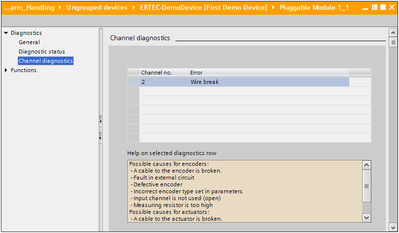
Siemens decodes the diagnostic as a “Wire Break,” and lists the channel that the diagnostic was generated from (in this case, Channel no. 2). When we triggered the new Manufacturer-Specific ExtChannelErrorType from Channel no. 3, it looked a little different:
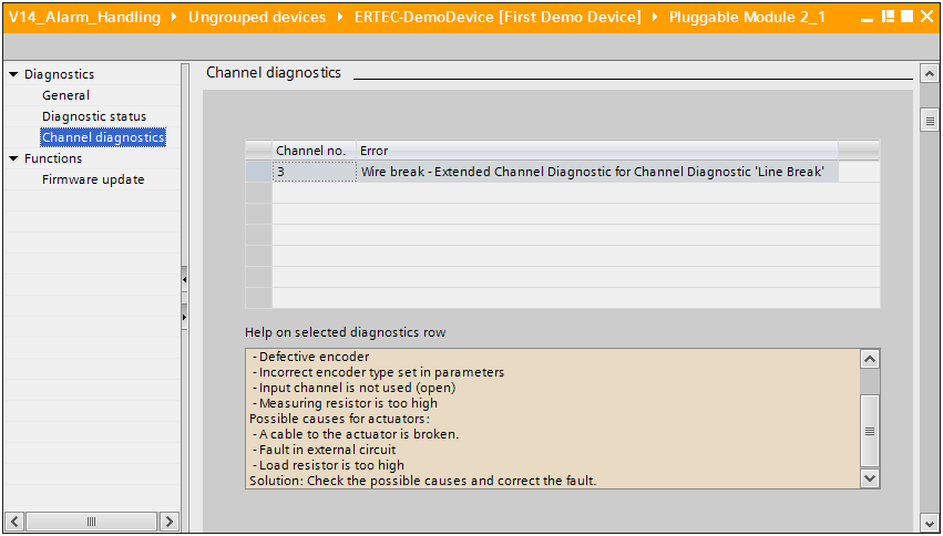
TIA Portal mapped the ExtChannelErrorType transmitted over the wire (0x0123) to the text description from the GSDML file. It saved the end user the headache of manually looking up the diagnostic code in a manual to figure out what broke. It’s a simple enough trick, but it’s one that can save time when minutes count to resolve unplanned downtime.
Summary
There’s more to this subject to talk about, but we’re running out of space here. Questions like “How is this different from a PROFINET Error?” (proper noun, capital “E”) or “Hey, you only showed me how to see errors, how can I handle them in my PLC’s application?” are a little too complex to handle in this article. For more information, drop us a line at the PROFI Interface Center, or check out PI North America’s suite of PROFINET Training courses. We’re always happy to help.
 Do you want to learn more about PROFINET?
The PROFI Interface Center has you covered with PROFINET Certified Network Engineer classes.
Our certification classes are intense, hands-on courses. You will learn how the underlying technology works from the application to the frame level. After passing both a practical and written exam, you become certified.
For more information, contact us or visit our website.